CLEARCERAM®-Z

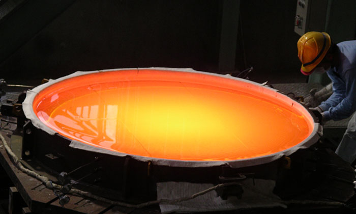
Glass-ceramic with an Ultra-Low Thermal Expansion Coefficient and developed by High Homogeneity melting and Precise Crystallization. 

Key Properties of CLEARCERAM®-Z

Ultra-Low Expansion Glass

  • Shows almost Zero Thermal Expansion over a wide temperature range & offers superior thermal shock resistance
  • CCZ-Regular offers lower thermal expansion across a wide temperature range
  • CCZ-HS offers lower thermal expansion near room temperature.
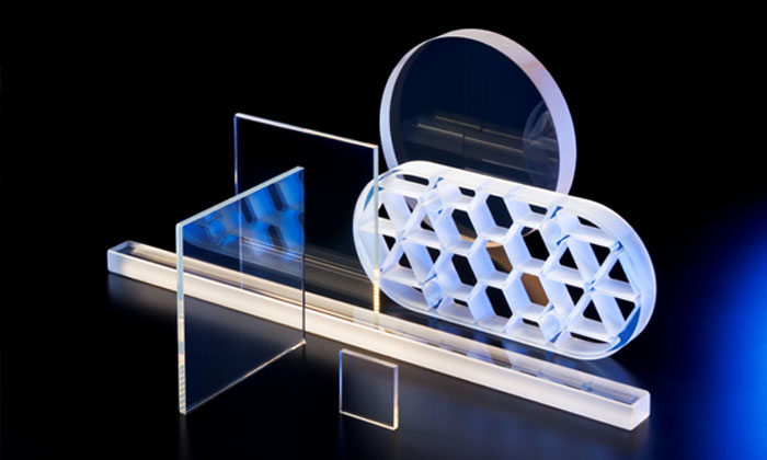
  • Superior Mechanical Properties – The crystal grain structure of prevents the propagation of microscopic cracks that can be caused in between machining processes. This allows CCZ to be processed into various shapes with high accuracy and elevated yield rates. CLEARCERAM®-Z is comprised of approximately 70% ceramic material, which makes the mechanical characteristics superior to regular amorphous glass when comparing properties such as Young’s Modulus, Rigidity, Bending Strength, and Knoop Hardness.
  • Excellent chemical resistance, durability, and stability in various cleaning and thin-film coating processes as the composition does not contain Na, K, B, F, or Pb.

Applications

CLEARCERAM®-Z is used for semiconductor stepper components, liquid crystal stepper components, optical flats, spacers, windows, interferometer components, laser refraction mirrors and suspensions, astronomical telescope mirrors, block gauges, long precision scales, optical pedestal platforms, and pedestals for precision equipment. This material is an ideal alternate to quartz glass, ceramics, or low thermal expansion alloys. Please contact us for additional details about CLEARCERAM®-Z- Ultra Low Expansion Glass.

Gallery

CLEARCERAM®-Z Papers

‘Laser Focus World – December 2015’

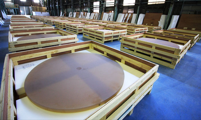
At the heart of the TMT are the 492 hexagonal mirrors that make up the telescope’s primary mirror. Ohara Inc. is supplying the 574 M1 segment mirror blanks needed for the telescope (Including spares) and has produced more than 100 mirror blanks already. Made of Ohara’s CLEARCERAM®-Z ultra-low expansion glass ceramic, each blank is 1.5 m in diameter and about 50 mm thick, according to Brion Hoffman, president of Ohara Corp.

(Courtesy of Laser Focus World and the TMT).


E6 Low Expansion Glass - OC’s Work with The University of Arizona

In 1982, Ohara supplied E6 Low Expansion Glass to The University of Arizona for  the first spin cast trial mirror, used in The Vatican Advanced Technology Telescope. Over the decades, Ohara’s E6 has been used in the Smithsonian Astrophysical Observatory, the Large Binocular Telescope, and the Multiple Mirror Telescope Conversion, to name a few. Currently, E6 Low Expansion Glass is being used to make the primary mirrors for the Giant Magellan Telescope (GMT)! The GMT is under construction at the Las Campanas Observatory in Chile. This segmented mirror telescope will utilize seven monolithic lightweight mirrors (the largest in the world): 6 off-axis 8.4 meter (27 ft.) in diameter mirror segments surrounding 1 single on-axis mirror segment, forming a single optical surface 24.5 meters (80 ft.) in diameter. 

E6 Low Expansion Glass - OC’s Work with National Geographic

National Geographic’s February 2024 issue includes the article, “A glass revolution is underway. Spoiler alert: it bends and bounces,” which features Ohara’s E6 Low Expansion Glass. The article highlights how E6 glass is melted and processed in Japan and serves a pivotal role in the spin-cast mirrors used in several of the world’s largest telescopes. National Geographic emphasizes that E6 glass is just one example of how glass is being reinvented to make huge technological and industrial advancements.

OPTICAL PROPERTIES

2.5 Temperature Coefficient of Refractive Index

Temperature coefficient of refractive index 〔Δn relT

The refractive index of glass changes with temperature. The amount of change in the refractive index due to temperature changes is expressed as the temperature coefficient of the refractive index, and is defined by Δn / ΔT from the curve showing the relationship between the glass temperature and the refractive index. Δn / ΔT changes depending on the measurement wavelength and temperature range, so the Abbe number also changes with temperature.
There are two ways of showing the temperature coefficient of refractive index; one is the relative coefficient, Δnrel/ΔT (10-6 K-1) measured in dry air (101.3 kPa) at same temperature as the glass, and the other is the absolute coefficient ,Δnabs/ΔT (10-6 K-1) measured under vacuum.

The temperature coefficient of refractive index of each glass type is measured as Δnabs/ΔT according to ISO 6760-1 and from this value the Δnrel/ΔT value normally used in optical design is calculated. The relationship between Δn abs/ΔT and Δn rel/ΔT is given by the following formula.

Formula for temperature coefficient of refractive index of glass

n :Refractive index of glass sample (in air, 25 ° C)

OPTICAL PROPERTIES

2.7 Internal Transmittance

Internal transmittance 〔 τi(10 mm)〕

“Internal transmittance” refers to the spectral transmittance of the glass itself, not including reflection losses at the optical glass-air interface; it indicates the transparency of the glass. Most optical glasses absorb a substantial amount of light in the near-ultraviolet region. For some glasses, especially those with a high refractive index, this absorption range also extends into the visible range. This absorption is not only caused by the composition of the glass; it is also affected by impurities in the glass, and varies slightly from melt to melt.

The spectral transmittance (including reflection loss) is measured based on the JOGIS-17 standard at wavelengths from 280 nm to 2400 nm in a pair of glass samples with different distances through which transmitted light passes. Then, the internal transmittance 〔τ<sub>i</sub>(10 mm)〕 at a glass sample thickness of 10 mm is calculated from the measurement data.

OPTICAL PROPERTIES

2.10 CCI (Color Contribution Index)

CCI

CCI (Color Contribution Index) is an index for predicting how much the color of a photograph taken using a certain lens system changes compared to the original color, due to the spectral characteristics of the lens. It is indicated by a set of 3 numbers for blue (B) / green (G) / red (R). Ohara uses this index to predict how much the color will change as a single glass element. For the measurement method, refer to JIS B 7097 “How to express the color characteristics of a photographic lens by the ISO color characteristic index (ISO / CCI)”. The numbers shown are calculated using the sum of the values of the internal transmittance of the glass sample every 10 nm and the average color film weighted spectral sensitivity, described in JIS. For example, B / G / R of 0/3/5, is shown in Fig. 4 in trilinear coordinates.

CCIE
OPTICAL PROPERTIES

2.2 Dispersion and Abbe Number

Dispersion and Abbe Number

Dispersion refers to the phenomenon arising from a variation in the refractive index depending on the wavelength. Here, nF-nC and nF’-nC’are displayed as the main dispersion. The Abbe number is an index of the magnitude of the variance and is also called the inverse dispersion rate. The larger the variance, the smaller the Abbe number.

Abbe Numbers Calcuation

The glass type data sheet indicates the dispersion, calculated from the refractive index to six decimal places . Abbe number is indicated to two decimal places, this is the result of the calculation from nd to six decimal places and the principal dispersion to six decimal places .

Two decimal places: This is the result of calculation from nd to six decimal places (with seven effective digits) and the principal dispersion to six decimal places (with four or more effective digits).

OPTICAL PROPERTIES

2.6 Relational Constant for Temperature Coefficient of the Refractive Index

Relational constant for temperature coefficient of the refractive index

The temperature coefficient of the absolute refractive index of glass for wavelengths not listed in the data sheet can be calculated as a function of wavelength and temperature. Ohara uses the following equation.

Equation for Temperature Coefficient of absolute refractive index of glass
(λ,T0) Refractive index at reference temperature
0 Reference temperature (°C) (Ohara defines this as 25°C)
T: Target temperature (°C)
λ: Vacuum wavelength (μm)
D0D1 D2E0 E1、λTK Constant (listed in the data sheet)

To determine the temperature coefficient of the relative refractive index, refer to the equation given in the previous section, “Temperature coefficient of the refractive index”.

OPTICAL PROPERTIES

2.1 Refractive Index

Refractive Index

When light enters the glass, it slows down inversely proportional to the refractive index compared to in a vacuum or in air. The refractive index of optical glass is usually expressed as the speed ratio of light in the air to themedium (glass sample).

The refractive index is measured by sending a predetermined wavelength of light into the sample and measuring theminimum deviation angle of the emitted light bent by refraction, according to JIS B 7071-1. For the 20 spectral lines shown in the table below, numerical values are shown to five decimal places. The refractive indices (principal refractive indices) for d-line (587.56 nm) and e-line (546.07 nm) are also shown to six decimal places.

Spectral Line Symbol t
Light Source Hg Hg Hg Hg Hg
Wavelength (nm) 2325.42 1970.09 1529.58 1128.64 1013.98
Spectral Line Symbol s A′ r C C′
Light Source Cs K He H Cd
Wavelength (nm) 852.11 768.19 706.52 656.27 643.85
Spectral Line Symbol He-Ne D d e F
Light Source レーザー Na He Hg H
Wavelength (nm) 852.11 589.29 587.56 546.07 486.13
Spectral Line Symbol F′ He-Cd g h i
Light Source Cd レーザー Hg Hg Hg
Wavelength (nm) 479.99 441.57 435.835 404.656 365.015
OPTICAL PROPERTIES

2.4 Disperson Formula Constant

The refractive index for wavelengths not listed in the data sheet can be calculated using the dispersion formula. The Sellmeier equation is used as a practical dispersion formula, as detailed below.

Sellmeier Equation
n : Refractive index to be calculated
λ : Arbitrary wavelength (μm)
A1、A2、A3、B1、B2、B3 Constant (listed in the data sheet)

Using this dispersion formula and the constants for each glass type, the refractive index of any wavelength in the standard measurement wavelength range (365 to 2325 nm) can be calculated with a calculation accuracy of ±5×10<sup>-6</sup>. However, for glass types for which the refractive indices for the entire standard measurement wavelength range are not listed in the data sheet, the applicable wavelength range of the dispersion formula is limited to the refractive index range listed in the data sheet.

OPTICAL PROPERTIES

2.8 Coloring

Coloring

Coloring refers to the degree of coloration of the optical glass and is determined by measuring the spectral transmittance, including reflection losses, for a glass sample with a thickness of 10 mm, according to JOGIS-02. From the spectral transmittance curve (Fig. 3), the wavelengths showing the transmittance of 80% and 5%, respectively, are rounded and displayed in 5 nm units. We use this rounding method: the range 0 nm to 2 nm counts as 0 nm, the range 3 nm to 7 nm counts as 5 nm, the range 8 nm to 10 nm counts as 10 nm . For example, if the wavelength with 80% transmittance is 403 nm and the wavelength with 5% transmittance is 357 nm, the coloring is shown as 405/355.

Optical Glass Coloring

For glass types with a high refractive index, nd ≥ 1.84, the reflection loss is large, so the wavelength showing transmittance of 70 % is used, instead of 80 %, and the value is shown in paranethesis. For example, (415).

OPTICAL PROPERTIES

2.9 Internal Transparency

Internal transparency〔λ0.800.05

As a simplified indicator of coloring, the wavelength values in nm at which
the internal transmittance of a 10 mm thick glass sample is 0.80 and 0.05
are indicated.

OPTICAL PROPERTIES

2.3 Partial dispersion ratio and anomalous dispersion

Partial dispersion ratio 〔θx, y〕 and anomalous dispersion 〔Δθx, y
Anomalous dispersion refers to how far away a glass is from the trend line between the partial dispersion ratio θx, y = (nx-ny) / (nF-nC) for wavelengths x and y and the Abbe number νd. In optical design, glass with anomalous dispersion is required to enable color correction of the secondary spectrum.
Therefore, we have released the θg, Fd diagram and the θC, td diagram as means to show the relationship between θx, y and νd of each glass type. In order to numerically express the anomalous dispersibility, 511605 (NSL 7) and 620363 (PBM 2) are used as reference glasses, and the straight line connecting these two glass types is considered the “normal” line. The difference between the “normal” line and the vertical coordinates θx, y of each glass type is calculated as anomalous dispersion Δθx, y (Fig. 2). In this catalog, the partial dispersion ratio is θg, F and θC, t, and the anomalous dispersion is Δθg, F and ΔθC, t.

Although NSL 7 and PBM 2 are not currently produced by Ohara, the conventional NSL 7 and PBM 2 values ​​(Table 2) are used as the reference values.

Reference Values

θc,t
θC,A'
θg,d
θg,F
θi,g
vd
NSL 7
0.8305
0.3492
1.2391
0.5436
1.2185
60.49
PBM 2
0.7168
0.3198
1.2894
0.5828
1.4214
36.26

g,Fd図とΔθg,F

2.3 Chart