4. Chemical Properties

There are some glasses that lack durability due to the chemical behavior of the constituents utilized in the composition. These glasses are influenced by water vapor, acid, gasses, etc., as well as ions in the polishing slurry. Consequently, dimming and staining will occur on the surfaces of these glasses during processing and storage. Since such phenomena have to do with surface conditions and environment, no single test can be accepted as a criterion of durability under all conditions. We listed resistance to water and acid by the powder test method and resistance to weather by the surface test method. We have also listed resistance to acid and phosphate, following the test method of ISO8424 and 9689.

4.1 Water Resistance [RW(p)] and Acid Resistance [RA(p)] (Powder Method)
The glass to be tested is crushed to 425μm ~ 600μm grains. A sample of this powder equivalent to the specific gravity in grams is placed on a platinum basket. This is put in a flask of silica glass containing the reagent and boiled for 60 minutes. The sample is then carefully dried and re-weighed to determine the loss of weight (percent) and classified as per Tables 1 and 2. The reagent used for the water resistance test is distilled water (pH 6.5 ~ 7.5). 1/100N nitric acid is used for the acid resistance test.

Table1 Water Resistance

Class123456
Loss of wt%<0.05

>0.05

<0.10

>0.01

<0.25

>0.25

<0.60

>0.60

<1.10

>1.10


Table2 Acid Resistance

Class123456
Loss of wt%<0.20

>0.20

<0.35

>0.35

<0.65

0.65>

1.2<

1.20>

2.20<

2.20>

4.2 Weathering Resistance [W(s)] (Surface Method)
This test is carried out by putting freshly polished glass plates in a chamber at +50°C, 85% humidity for 24 hours. If the glass surface is severely attacked, another 6 hour test is carried out with new pieces. The classification into four groups is then obtained by inspecting the treated surface through a 50x microscope as per Table 3.

Table 3

ClassClassification
1

When there is no fading on the glass exposed in

the chamber for 24 hours and observed at 6000

luxes.

2

When there is no fading observed on the glass

exposed in the chamber for 24 hours at 1500 luxes but fading

is observed at 6000 luxes.

3

When fading is observed on the glass exposed in

the chamber for 24 hours when inspected at 1500

luxes.

4

When fading is observed on the glass exposed in

the chamber for 6 hours when inspected at 1500

luxes.

4.3 lSO Method

4.3.1 Acid Resistance (SR)
Glass samples with dimensions of 30 x 30 x 2 mm are prepared. The surface of these samples are polished to the specified polishing conditions. They are hung by platinum wire into nitric acid solution (pH 0.3) or acetic acid buffer solution (pH 4.6) at 25degC for the length of times specified (10 minutes, 100 minutes, 16 hours or 100 hours). After this treatment, the loss of mass of the sample is determined using an analytical balance. Calculation of the time t0.1 in hours, necessary to etch a surface layer to a depth of 0.1μm is done using the following formula:

t 0.1= (tedS) / {(m1-m2)100}

0.1 : the time (h) necessary to etch a surface layer to a depth of0.1μm.

te :the time (h) for attack in the experiment

the specific gravity of the sample

S :the surface area (cm2 ) of the sample

m1 : the mass (mg) of the sample before the test

m2 : the mass (mg) of the sample after the test

The calculation is carried out by use of the value of the loss of mass which is ob-served by the minimum test condition (i.e., test solution and test time) for obtaining a loss of mass greater than 1 mg / sample. If the loss of mass is less than 1mg / sample after 100 hours exposure to pH 0.3, this value shall be accepted. The acid resistance class SR is obtained by comparison of the pH of the test solution and the time required for the attack to a depth of 0.1μm (h) with time scales given in the classification Table 4.

Table 4

Acid resistance class

SR

12345 51 5253
pH of the attacking solution0.30.30.30.30.34.64.64.64.6

 Time t0.1  needed to etch

to a depth of 0.1μm (h)

>100100 ~1010 ~11 ~0.1<0.1 >1010 ~1 1 ~0.1<0.1

In addition, changes in the surface of the sample following the treatment are qualitatively evaluated with the naked eye. Additional classification numbers are given ac-cording to Table 5.

Table 5

Additional NumberChanges in the Surface
.0No visible changes
.1

Clear, but irregular surface (wavy,

pockmarked)

.2

Interference colors (slight selective

leaching)

.3

Tenacious thin whitish layer (stronger

selective

.4

Loosely adhering thick layer (Surface

crust)

4.3.2 Phosphate Resistance (PR)
Glass samples with dimensions of 30 x 30 x 2 mm are prepared and all surfaces are polished to given specifications. They are hung by platinum wire into aqueous solution containing 0.01 mol / l purified tripolyphosphate at 50degC for specified lengths of time (15 minutes, 1 hour, 4 hours or 16 hours). After this treatment, the loss of mass of the sample is determined using an analytical balance. Calculation of the time t0.1 necessary to etch a surface layer to a depth of 0.1μm is made using the same formula which is used for obtaining the acid resistance (SR) in the previous section. In this case, however, the time units are minutes. The calculation is carried out, as a rule, using the value of the loss of mass which is observed under the minimum test conditions (i.e., test solution and test time for obtaining a loss of mass greater than 1 mg / sample). The phosphate resistance class PR is obtained by comparison of the time required for the attack to a depth of 0.1μm (min) with time scales given in classification Table 6.

Table 6

Phosphate resistance class PR1234

 Time t0.1 needed to etch to a

depth of 0.1μm/min)

>240240 ~60 60 ~15<15

Next, changes in the surface of the sample following the treatment are qualitatively evaluated with the naked eye. Additional classification numbers are given in addition to the class number according to Table 5used for obtaining the acid resistance (SR) in the previous section. For example, it is indicated that the phosphate resistance class is PR 2.0 for optical glass which needs 120 minutes for attack to a depth of 0.1μm , with no visible changes in the surface after the attack.

OPTICAL PROPERTIES

2.5 Temperature Coefficient of Refractive Index

Temperature coefficient of refractive index 〔Δn relT

The refractive index of glass changes with temperature. The amount of change in the refractive index due to temperature changes is expressed as the temperature coefficient of the refractive index, and is defined by Δn / ΔT from the curve showing the relationship between the glass temperature and the refractive index. Δn / ΔT changes depending on the measurement wavelength and temperature range, so the Abbe number also changes with temperature.
There are two ways of showing the temperature coefficient of refractive index; one is the relative coefficient, Δnrel/ΔT (10-6 K-1) measured in dry air (101.3 kPa) at same temperature as the glass, and the other is the absolute coefficient ,Δnabs/ΔT (10-6 K-1) measured under vacuum.

The temperature coefficient of refractive index of each glass type is measured as Δnabs/ΔT according to ISO 6760-1 and from this value the Δnrel/ΔT value normally used in optical design is calculated. The relationship between Δn abs/ΔT and Δn rel/ΔT is given by the following formula.

Formula for temperature coefficient of refractive index of glass

n :Refractive index of glass sample (in air, 25 ° C)

OPTICAL PROPERTIES

2.7 Internal Transmittance

Internal transmittance 〔 τi(10 mm)〕

“Internal transmittance” refers to the spectral transmittance of the glass itself, not including reflection losses at the optical glass-air interface; it indicates the transparency of the glass. Most optical glasses absorb a substantial amount of light in the near-ultraviolet region. For some glasses, especially those with a high refractive index, this absorption range also extends into the visible range. This absorption is not only caused by the composition of the glass; it is also affected by impurities in the glass, and varies slightly from melt to melt.

The spectral transmittance (including reflection loss) is measured based on the JOGIS-17 standard at wavelengths from 280 nm to 2400 nm in a pair of glass samples with different distances through which transmitted light passes. Then, the internal transmittance 〔τ<sub>i</sub>(10 mm)〕 at a glass sample thickness of 10 mm is calculated from the measurement data.

OPTICAL PROPERTIES

2.10 CCI (Color Contribution Index)

CCI

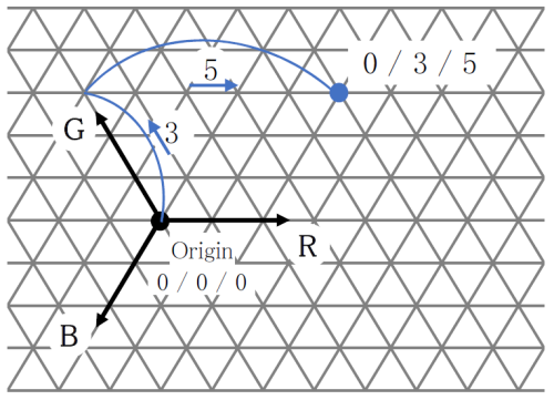
CCI (Color Contribution Index) is an index for predicting how much the color of a photograph taken using a certain lens system changes compared to the original color, due to the spectral characteristics of the lens. It is indicated by a set of 3 numbers for blue (B) / green (G) / red (R). Ohara uses this index to predict how much the color will change as a single glass element. For the measurement method, refer to JIS B 7097 “How to express the color characteristics of a photographic lens by the ISO color characteristic index (ISO / CCI)”. The numbers shown are calculated using the sum of the values of the internal transmittance of the glass sample every 10 nm and the average color film weighted spectral sensitivity, described in JIS. For example, B / G / R of 0/3/5, is shown in Fig. 4 in trilinear coordinates.

CCIE
OPTICAL PROPERTIES

2.2 Dispersion and Abbe Number

Dispersion and Abbe Number

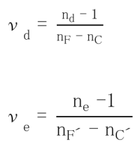
Dispersion refers to the phenomenon arising from a variation in the refractive index depending on the wavelength. Here, nF-nC and nF’-nC’are displayed as the main dispersion. The Abbe number is an index of the magnitude of the variance and is also called the inverse dispersion rate. The larger the variance, the smaller the Abbe number.

Abbe Numbers Calcuation

The glass type data sheet indicates the dispersion, calculated from the refractive index to six decimal places . Abbe number is indicated to two decimal places, this is the result of the calculation from nd to six decimal places and the principal dispersion to six decimal places .

Two decimal places: This is the result of calculation from nd to six decimal places (with seven effective digits) and the principal dispersion to six decimal places (with four or more effective digits).

OPTICAL PROPERTIES

2.6 Relational Constant for Temperature Coefficient of the Refractive Index

Relational constant for temperature coefficient of the refractive index

The temperature coefficient of the absolute refractive index of glass for wavelengths not listed in the data sheet can be calculated as a function of wavelength and temperature. Ohara uses the following equation.

Equation for Temperature Coefficient of absolute refractive index of glass
(λ,T0) Refractive index at reference temperature
0 Reference temperature (°C) (Ohara defines this as 25°C)
T: Target temperature (°C)
λ: Vacuum wavelength (μm)
D0D1 D2E0 E1、λTK Constant (listed in the data sheet)

To determine the temperature coefficient of the relative refractive index, refer to the equation given in the previous section, “Temperature coefficient of the refractive index”.

OPTICAL PROPERTIES

2.1 Refractive Index

Refractive Index

When light enters the glass, it slows down inversely proportional to the refractive index compared to in a vacuum or in air. The refractive index of optical glass is usually expressed as the speed ratio of light in the air to themedium (glass sample).

The refractive index is measured by sending a predetermined wavelength of light into the sample and measuring theminimum deviation angle of the emitted light bent by refraction, according to JIS B 7071-1. For the 20 spectral lines shown in the table below, numerical values are shown to five decimal places. The refractive indices (principal refractive indices) for d-line (587.56 nm) and e-line (546.07 nm) are also shown to six decimal places.

Spectral Line Symbol t
Light Source Hg Hg Hg Hg Hg
Wavelength (nm) 2325.42 1970.09 1529.58 1128.64 1013.98
Spectral Line Symbol s A′ r C C′
Light Source Cs K He H Cd
Wavelength (nm) 852.11 768.19 706.52 656.27 643.85
Spectral Line Symbol He-Ne D d e F
Light Source レーザー Na He Hg H
Wavelength (nm) 852.11 589.29 587.56 546.07 486.13
Spectral Line Symbol F′ He-Cd g h i
Light Source Cd レーザー Hg Hg Hg
Wavelength (nm) 479.99 441.57 435.835 404.656 365.015
OPTICAL PROPERTIES

2.4 Disperson Formula Constant

The refractive index for wavelengths not listed in the data sheet can be calculated using the dispersion formula. The Sellmeier equation is used as a practical dispersion formula, as detailed below.

Sellmeier Equation
n : Refractive index to be calculated
λ : Arbitrary wavelength (μm)
A1、A2、A3、B1、B2、B3 Constant (listed in the data sheet)

Using this dispersion formula and the constants for each glass type, the refractive index of any wavelength in the standard measurement wavelength range (365 to 2325 nm) can be calculated with a calculation accuracy of ±5×10<sup>-6</sup>. However, for glass types for which the refractive indices for the entire standard measurement wavelength range are not listed in the data sheet, the applicable wavelength range of the dispersion formula is limited to the refractive index range listed in the data sheet.

OPTICAL PROPERTIES

2.8 Coloring

Coloring

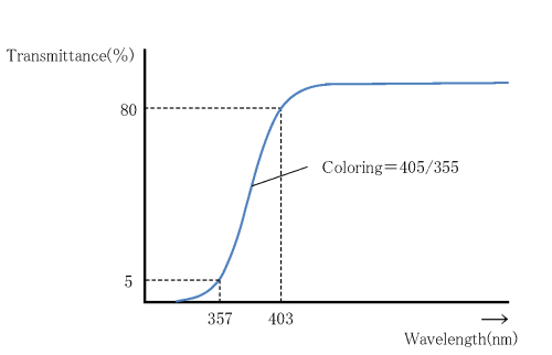
Coloring refers to the degree of coloration of the optical glass and is determined by measuring the spectral transmittance, including reflection losses, for a glass sample with a thickness of 10 mm, according to JOGIS-02. From the spectral transmittance curve (Fig. 3), the wavelengths showing the transmittance of 80% and 5%, respectively, are rounded and displayed in 5 nm units. We use this rounding method: the range 0 nm to 2 nm counts as 0 nm, the range 3 nm to 7 nm counts as 5 nm, the range 8 nm to 10 nm counts as 10 nm . For example, if the wavelength with 80% transmittance is 403 nm and the wavelength with 5% transmittance is 357 nm, the coloring is shown as 405/355.

Optical Glass Coloring

For glass types with a high refractive index, nd ≥ 1.84, the reflection loss is large, so the wavelength showing transmittance of 70 % is used, instead of 80 %, and the value is shown in paranethesis. For example, (415).

OPTICAL PROPERTIES

2.9 Internal Transparency

Internal transparency〔λ0.800.05

As a simplified indicator of coloring, the wavelength values in nm at which
the internal transmittance of a 10 mm thick glass sample is 0.80 and 0.05
are indicated.

OPTICAL PROPERTIES

2.3 Partial dispersion ratio and anomalous dispersion

Partial dispersion ratio 〔θx, y〕 and anomalous dispersion 〔Δθx, y
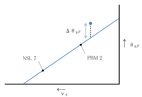
Anomalous dispersion refers to how far away a glass is from the trend line between the partial dispersion ratio θx, y = (nx-ny) / (nF-nC) for wavelengths x and y and the Abbe number νd. In optical design, glass with anomalous dispersion is required to enable color correction of the secondary spectrum.
Therefore, we have released the θg, Fd diagram and the θC, td diagram as means to show the relationship between θx, y and νd of each glass type. In order to numerically express the anomalous dispersibility, 511605 (NSL 7) and 620363 (PBM 2) are used as reference glasses, and the straight line connecting these two glass types is considered the “normal” line. The difference between the “normal” line and the vertical coordinates θx, y of each glass type is calculated as anomalous dispersion Δθx, y (Fig. 2). In this catalog, the partial dispersion ratio is θg, F and θC, t, and the anomalous dispersion is Δθg, F and ΔθC, t.

Although NSL 7 and PBM 2 are not currently produced by Ohara, the conventional NSL 7 and PBM 2 values ​​(Table 2) are used as the reference values.

Reference Values

θc,t
θC,A'
θg,d
θg,F
θi,g
vd
NSL 7
0.8305
0.3492
1.2391
0.5436
1.2185
60.49
PBM 2
0.7168
0.3198
1.2894
0.5828
1.4214
36.26

g,Fd図とΔθg,F

2.3 Chart