Ohara Supports NASA’s Nancy Grace Roman Space Telescope

Ohara optical glass selected for Coronagraph Instrument
and Wide Field Instrument of NASA’s Nancy Grace Roman Space Telescope.

Ohara Optical Glasses Featured in both the Coronagraph Instrument and Wide Field Instrument of NASA's Nancy Grace Roman Space Telescope

Branchburg, New Jersey, USA / Sagamihara, Japan –  September 30, 2026 – Ohara Corporation is proud to announce that several Ohara optical glass types are incorporated into two key instruments aboard NASA’s Nancy Grace Roman Space Telescope, which successfully launched on August 30, 2026. The observatory carries two highly advanced optical systems: the Wide Field Instrument (WFI) and the Coronagraph Instrument (CGI), both designed to advance humanity’s understanding of exoplanets, dark energy, dark matter, and the evolution of the universe. Ohara optical glasses contributed to the development, testing, and flight hardware associated with these groundbreaking instruments. [1-4]

Nancy Grace Roman Space Telescope
Nancy Grace Roman Space Telescope. Image courtesy of NASA.

The Roman Coronagraph Instrument

The Roman Coronagraph Instrument (CGI) is designed to suppress the overwhelming light of distant stars, enabling astronomers to directly observe planets and dust disks orbiting those stars. By combining advanced masks, prisms, detectors, and deformable mirrors, the instrument is expected to achieve performance approximately 100 to 1,000 times greater than previous space-based coronagraph systems. The technologies demonstrated by the Coronagraph Instrument are expected to help pave the way for future space observatories capable of directly imaging Earth-like planets around nearby stars. [1,2]

The Roman Coronagraph Instrument incorporates Ohara radiation-resistant optical glass within its optical system. These specialized glass types were selected to withstand the radiation environment encountered during long-duration space missions while maintaining the exceptionally high optical performance required for direct imaging of exoplanets and circumstellar disks. These advanced materials help support the demanding optical requirements of the Coronagraph Instrument.
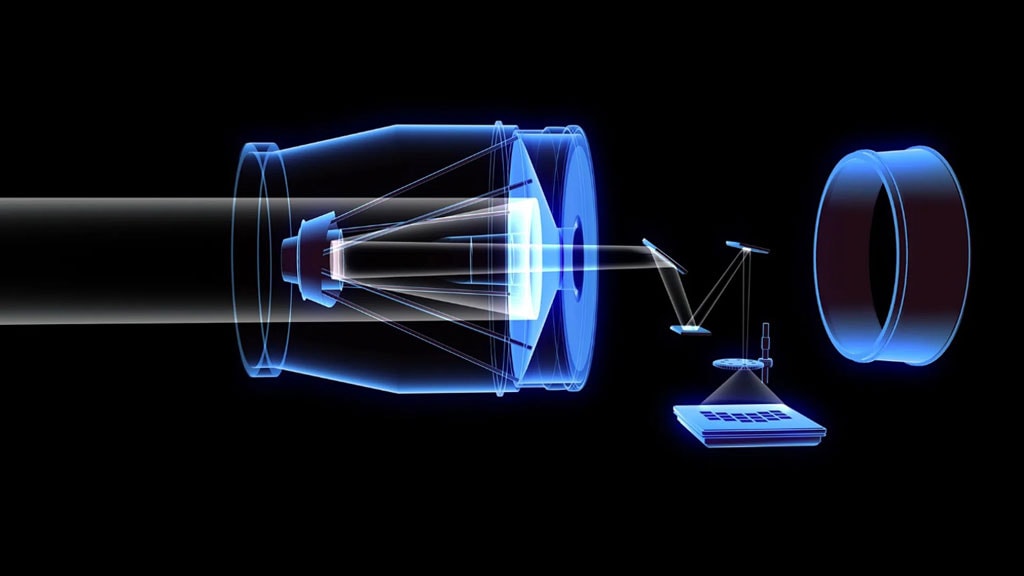
Roman Wide Field Instrument
Artist depiction of the Roman Wide Field Instrument. Image courtesy of NASA.

The Roman Wide Field Instrument

Integrated alongside the Coronagraph Instrument (CGI), the Wide Field Instrument (WFI) is a 300-megapixel near-infrared camera and spectroscopic system. The WFI provides a 0.281-square-degree field of view, with imaging and slitless spectroscopy modes supporting dark energy, exoplanet microlensing, and near-infrared surveys. [3,4]

The WFI incorporates a two-prism spectroscopic assembly utilizing Ohara optical glass in combination with calcium fluoride. This optical system will support broad astronomical surveys and the analysis of faint infrared signals from across the universe.
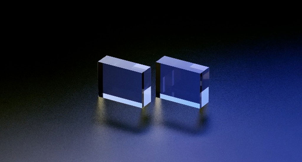
Ohara’s radiation – resistant optical glass

Ohara Optical Materials in the Roman Mission

A number of Ohara optical glass types were utilized during instrument development, optical testing, qualification, and mission-related activities associated with the Roman Space Telescope program. Radiation-resistant Ohara glass types were chosen to provide optical stability in the challenging radiation environment encountered during long-duration space missions. These specialized materials help enable the precision and reliability required for next-generation astronomical observations.

Supporting Future Scientific Discovery

The Nancy Grace Roman Space Telescope represents one of NASA’s most ambitious astrophysics missions. Through the supply of advanced optical glass materials used in both the Roman Coronagraph Instrument and the Wide Field Instrument, Ohara is honored to contribute to a mission that may transform our understanding of planetary systems, galaxy formation, dark energy, dark matter, and the origins of the universe. [1-4]


For more than 90 years, Ohara has developed specialty optical materials that enable scientific innovation, advanced imaging systems, semiconductor manufacturing, aerospace exploration, and life science technologies around the world. The Roman mission represents another example of how advanced optical materials help expand the boundaries of human knowledge.

About OHARA Corporation

Ohara Corporation is the U.S. subsidiary of Ohara Inc. and serves customers throughout North America, South America, and the Middle East. The company supplies advanced optical glass, glass ceramics, fused silica, polished substrates, and specialty optical materials for aerospace, semiconductor, life science, metrology, and industrial optics applications.

About Ohara Inc.

Ohara Inc., headquartered in Japan, is a global manufacturer of optical glass, specialty glass, fused silica, and glass ceramic materials. The company offers a broad portfolio of precision optical materials, including radiation-resistant optical glass products for demanding aerospace and scientific applications.

Editor's Notes

  • References to NASA missions and instruments are provided for informational purposes only and do not imply NASA endorsement of Ohara Corporation or its products. [5,6]
  • NASA images are reproduced for factual and informational purposes. NASA is acknowledged as the source. Users should confirm that each selected image is NASA-owned and does not contain third-party copyrighted material or an identifiable person requiring separate clearance. [5]

References

  1. Spectroscopy and Polarimetry Design and Flight Instrument Calibration for the Roman Coronagraph Instrument.
    Tyler D. Groff, Neil T. Zimmerman, Evan Bray, et al. Journal of Astronomical Telescopes, Instruments, and Systems (JATIS), Vol. 11, No. 3, Article 031510. SPIE, 2025.
    Available at: SPIE Digital Library – Roman Coronagraph Instrument
  2. Compact Prism Assembly for Slit-Less Spectroscopy Capability in Roman Wide Field Instrument.
    Bente H. Eegholm, Catherine T. Marx, Victor J. Chambers, et al. Journal of Astronomical Telescopes, Instruments, and Systems (JATIS), Vol. 11, No. 2, Article 025001. SPIE, 2025.
    Available at: SPIE Digital Library – Roman Wide Field Instrument Prism Assembly
  3. The Roman Coronagraph Instrument. NASA Jet Propulsion Laboratory.
    Available at: NASA JPL Roman Coronagraph Instrument
  4. Coronagraph. NASA Science, Nancy Grace Roman Space Telescope.
    Available at: NASA Science Roman Coronagraph
  5. Instruments and Capabilities. Roman Space Telescope / NASA Goddard Space Flight Center.
    Available at: NASA Roman Instruments and Capabilities
  6. Roman Technical Information. NASA Science, Nancy Grace Roman Space Telescope.
    Available at: NASA Roman Technical Information
  7. NASA Images and Media Usage Guidelines. NASA Brand Center.
    Available at: NASA Images and Media Guidelines [nasa.gov]
  8. NASA Brand Guidelines. NASA Brand Center.
    Available at: NASA Brand Guidelines [nasa.gov]
OPTICAL PROPERTIES

2.5 Temperature Coefficient of Refractive Index

Temperature coefficient of refractive index 〔Δn rel/ΔT〕

The refractive index of glass changes with temperature. The amount of change in the refractive index due to temperature changes is expressed as the temperature coefficient of the refractive index, and is defined by Δn / ΔT from the curve showing the relationship between the glass temperature and the refractive index. Δn / ΔT changes depending on the measurement wavelength and temperature range, so the Abbe number also changes with temperature.
There are two ways of showing the temperature coefficient of refractive index; one is the relative coefficient, Δnrel/ΔT (10-6 K-1) measured in dry air (101.3 kPa) at same temperature as the glass, and the other is the absolute coefficient ,Δnabs/ΔT (10-6 K-1) measured under vacuum.

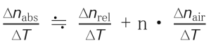
The temperature coefficient of refractive index of each glass type is measured as Δnabs/ΔT according to ISO 6760-1 and from this value the Δnrel/ΔT value normally used in optical design is calculated. The relationship between Δn abs/ΔT and Δn rel/ΔT is given by the following formula.

Formula for temperature coefficient of refractive index of glass

n :Refractive index of glass sample (in air, 25 ° C)

OPTICAL PROPERTIES

2.7 Internal Transmittance

Internal transmittance 〔 τi(10 mm)〕

“Internal transmittance” refers to the spectral transmittance of the glass itself, not including reflection losses at the optical glass-air interface; it indicates the transparency of the glass. Most optical glasses absorb a substantial amount of light in the near-ultraviolet region. For some glasses, especially those with a high refractive index, this absorption range also extends into the visible range. This absorption is not only caused by the composition of the glass; it is also affected by impurities in the glass, and varies slightly from melt to melt.

The spectral transmittance (including reflection loss) is measured based on the JOGIS-17 standard at wavelengths from 280 nm to 2400 nm in a pair of glass samples with different distances through which transmitted light passes. Then, the internal transmittance 〔τ<sub>i</sub>(10 mm)〕 at a glass sample thickness of 10 mm is calculated from the measurement data.

OPTICAL PROPERTIES

2.6 Relational Constant for Temperature Coefficient of the Refractive Index

Relational constant for temperature coefficient of the refractive index

The temperature coefficient of the absolute refractive index of glass for wavelengths not listed in the data sheet can be calculated as a function of wavelength and temperature. Ohara uses the following equation.

Equation for Temperature Coefficient of absolute refractive index of glass
n(λ,T0): Refractive index at reference temperature
T0: Reference temperature (°C) (Ohara defines this as 25°C)
T: Target temperature (°C)
λ: Vacuum wavelength (μm)
D0、D1、 D2、E0、 E1、λTK: Constant (listed in the data sheet)

To determine the temperature coefficient of the relative refractive index, refer to the equation given in the previous section, “Temperature coefficient of the refractive index”.

OPTICAL PROPERTIES

2.9 Internal Transparency

Internal transparency〔λ0.80/λ0.05〕

As a simplified indicator of coloring, the wavelength values in nm at which
the internal transmittance of a 10 mm thick glass sample is 0.80 and 0.05
are indicated.

OPTICAL PROPERTIES

2.8 Coloring

Coloring

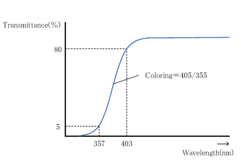
Coloring refers to the degree of coloration of the optical glass and is determined by measuring the spectral transmittance, including reflection losses, for a glass sample with a thickness of 10 mm, according to JOGIS-02. From the spectral transmittance curve (Fig. 3), the wavelengths showing the transmittance of 80% and 5%, respectively, are rounded and displayed in 5 nm units. We use this rounding method: the range 0 nm to 2 nm counts as 0 nm, the range 3 nm to 7 nm counts as 5 nm, the range 8 nm to 10 nm counts as 10 nm . For example, if the wavelength with 80% transmittance is 403 nm and the wavelength with 5% transmittance is 357 nm, the coloring is shown as 405/355.

Optical Glass Coloring

For glass types with a high refractive index, nd ≥ 1.84, the reflection loss is large, so the wavelength showing transmittance of 70 % is used, instead of 80 %, and the value is shown in paranethesis. For example, (415).

OPTICAL PROPERTIES

2.10 CCI (Color Contribution Index)

CCI

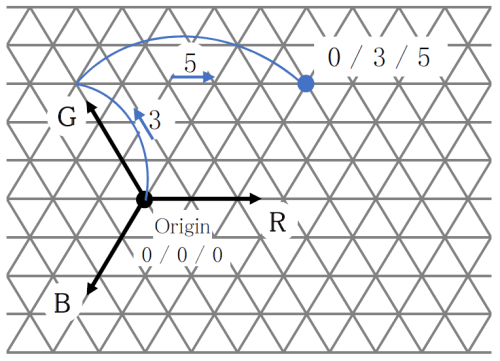
CCI (Color Contribution Index) is an index for predicting how much the color of a photograph taken using a certain lens system changes compared to the original color, due to the spectral characteristics of the lens. It is indicated by a set of 3 numbers for blue (B) / green (G) / red (R). Ohara uses this index to predict how much the color will change as a single glass element. For the measurement method, refer to JIS B 7097 “How to express the color characteristics of a photographic lens by the ISO color characteristic index (ISO / CCI)”. The numbers shown are calculated using the sum of the values of the internal transmittance of the glass sample every 10 nm and the average color film weighted spectral sensitivity, described in JIS. For example, B / G / R of 0/3/5, is shown in Fig. 4 in trilinear coordinates.

CCIE
OPTICAL PROPERTIES

2.1 Refractive Index

Refractive Index

When light enters the glass, it slows down inversely proportional to the refractive index compared to in a vacuum or in air. The refractive index of optical glass is usually expressed as the speed ratio of light in the air to themedium (glass sample).

The refractive index is measured by sending a predetermined wavelength of light into the sample and measuring theminimum deviation angle of the emitted light bent by refraction, according to JIS B 7071-1. For the 20 spectral lines shown in the table below, numerical values are shown to five decimal places. The refractive indices (principal refractive indices) for d-line (587.56 nm) and e-line (546.07 nm) are also shown to six decimal places.

Spectral Line Symbol t
Light Source Hg Hg Hg Hg Hg
Wavelength (nm) 2325.42 1970.09 1529.58 1128.64 1013.98
Spectral Line Symbol s A′ r C C′
Light Source Cs K He H Cd
Wavelength (nm) 852.11 768.19 706.52 656.27 643.85
Spectral Line Symbol He-Ne D d e F
Light Source レーザー Na He Hg H
Wavelength (nm) 632.8 589.29 587.56 546.07 486.13
Spectral Line Symbol F′ He-Cd g h i
Light Source Cd レーザー Hg Hg Hg
Wavelength (nm) 479.99 441.57 435.835 404.656 365.015
OPTICAL PROPERTIES

2.2 Dispersion and Abbe Number

Dispersion and Abbe Number

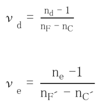
Dispersion refers to the phenomenon arising from a variation in the refractive index depending on the wavelength. Here, nF-nC and nF’-nC’are displayed as the main dispersion. The Abbe number is an index of the magnitude of the variance and is also called the inverse dispersion rate. The larger the variance, the smaller the Abbe number.

Abbe Numbers Calcuation

The glass type data sheet indicates the dispersion, calculated from the refractive index to six decimal places . Abbe number is indicated to two decimal places, this is the result of the calculation from nd to six decimal places and the principal dispersion to six decimal places .

Two decimal places: This is the result of calculation from nd to six decimal places (with seven effective digits) and the principal dispersion to six decimal places (with four or more effective digits).

OPTICAL PROPERTIES

2.3 Partial dispersion ratio and anomalous dispersion

Partial dispersion ratio 〔θx, y〕 and anomalous dispersion 〔Δθx, y〕
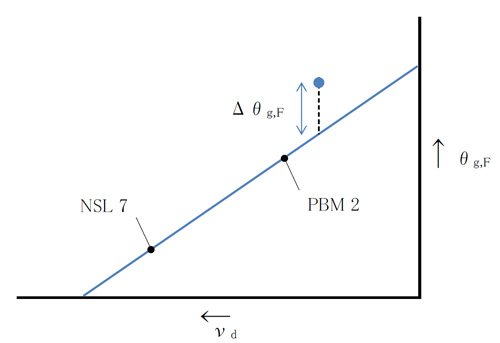
Anomalous dispersion refers to how far away a glass is from the trend line between the partial dispersion ratio θx, y = (nx-ny) / (nF-nC) for wavelengths x and y and the Abbe number νd. In optical design, glass with anomalous dispersion is required to enable color correction of the secondary spectrum.
Therefore, we have released the θg, F-νd diagram and the θC, t-νd diagram as means to show the relationship between θx, y and νd of each glass type. In order to numerically express the anomalous dispersibility, 511605 (NSL 7) and 620363 (PBM 2) are used as reference glasses, and the straight line connecting these two glass types is considered the “normal” line. The difference between the “normal” line and the vertical coordinates θx, y of each glass type is calculated as anomalous dispersion Δθx, y (Fig. 2). In this catalog, the partial dispersion ratio is θg, F and θC, t, and the anomalous dispersion is Δθg, F and ΔθC, t.

Although NSL 7 and PBM 2 are not currently produced by Ohara, the conventional NSL 7 and PBM 2 values ​​(Table 2) are used as the reference values.

Reference Values

θc,t
θC,A'
θg,d
θg,F
θi,g
vd
NSL 7
0.8305
0.3492
1.2391
0.5436
1.2185
60.49
PBM 2
0.7168
0.3198
1.2894
0.5828
1.4214
36.26

>θg,F-νd図とΔθg,F

2.3 Chart
OPTICAL PROPERTIES

2.4 Disperson Formula Constant

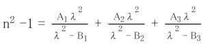
The refractive index for wavelengths not listed in the data sheet can be calculated using the dispersion formula. The Sellmeier equation is used as a practical dispersion formula, as detailed below.

Sellmeier Equation
n : Refractive index to be calculated
λ : Arbitrary wavelength (μm)
A1、A2、A3、B1、B2、B3 : Constant (listed in the data sheet)

Using this dispersion formula and the constants for each glass type, the refractive index of any wavelength in the standard measurement wavelength range (365 to 2325 nm) can be calculated with a calculation accuracy of ±5×10<sup>-6</sup>. However, for glass types for which the refractive indices for the entire standard measurement wavelength range are not listed in the data sheet, the applicable wavelength range of the dispersion formula is limited to the refractive index range listed in the data sheet.